Circuit and wiring
One ESP32, eight servos, two IMUs, a current sensor and a 2S battery. Schematic, wiring map, power board and a safe bring-up, step by step.
On this page
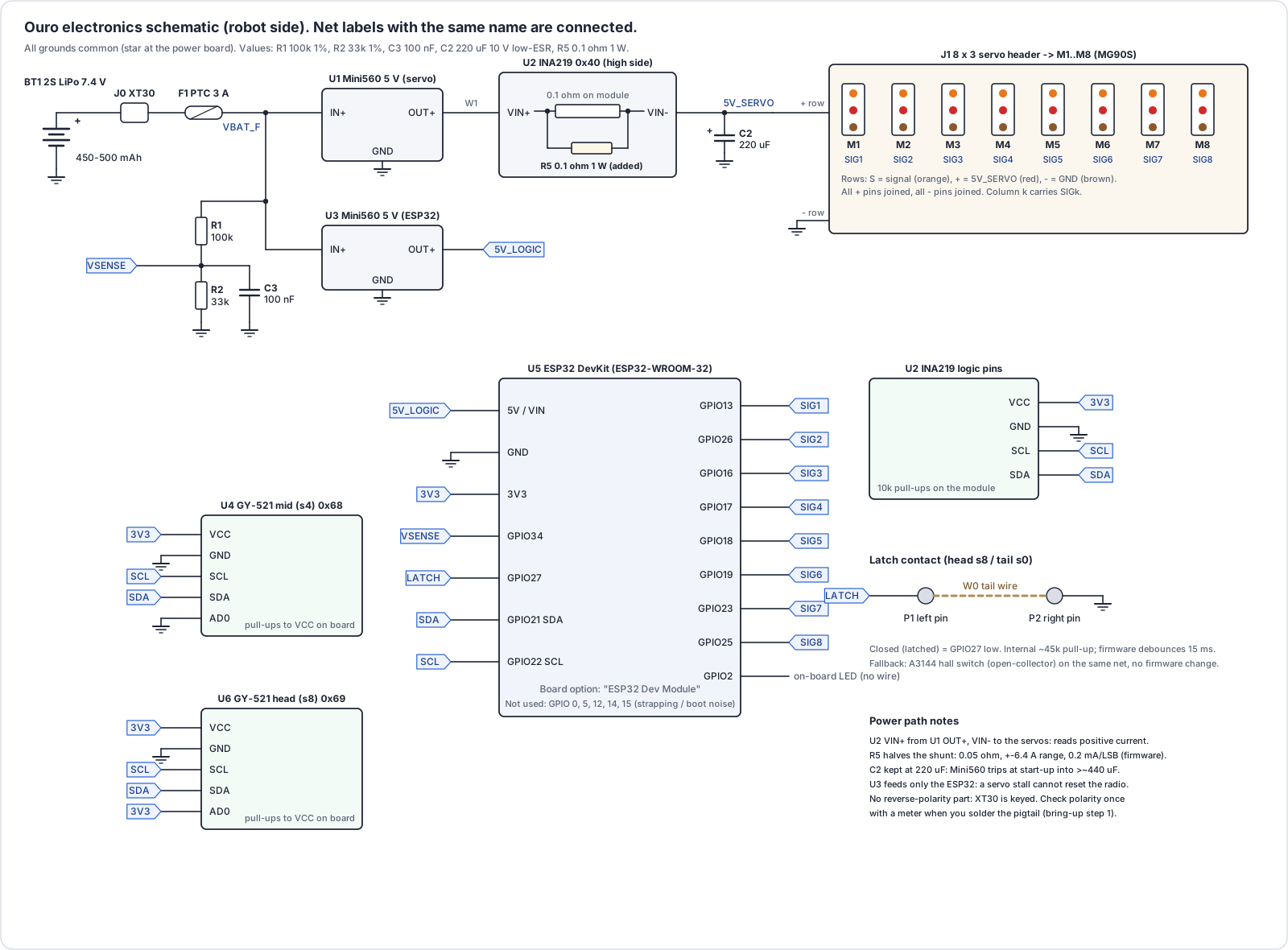
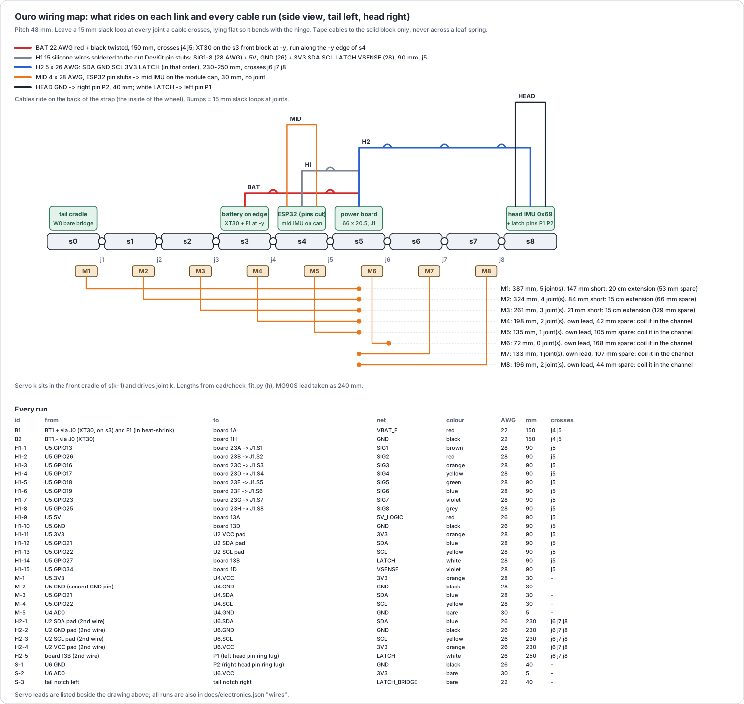
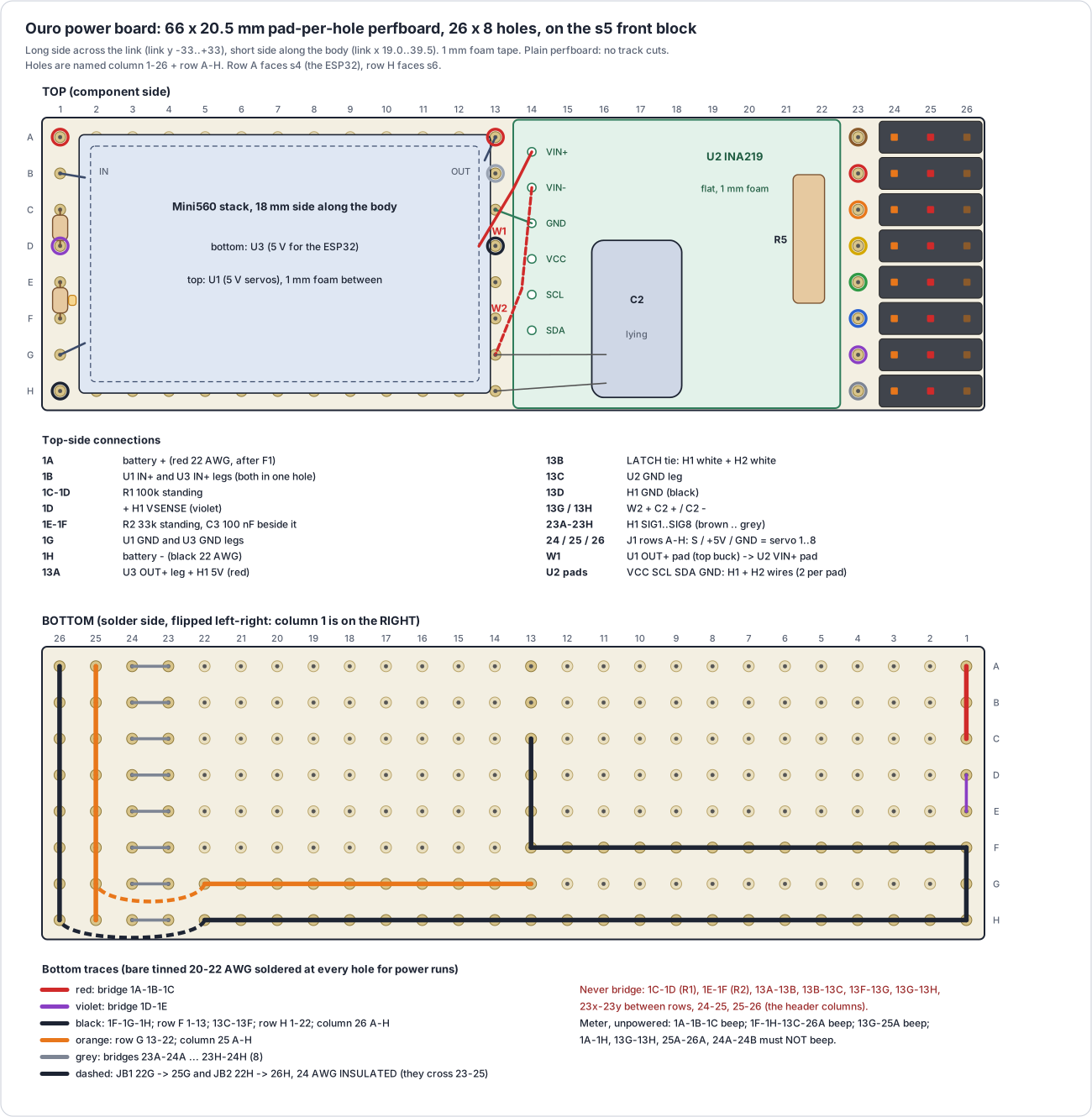
This page takes you from a bag of parts to a robot that talks to your computer. You get the whole circuit in one picture, a hole-by-hole build of the one board you solder, where every wire runs along the strap, and a bring-up sequence with the meter reading you should see at each step. The reference tables (pin map, power budget, firmware behaviour, packet formats, netlist) sit at the end for when you need them.
The circuit is new and has few builds behind it, so treat the meter readings in the bring-up as gates: do not move to the next step until you get the reading the table gives.
What you are building
Drawings: schematic.svg, wiring.svg (where every cable runs along the strap), perfboard.svg (the power board, hole by hole). The netlist, pin map and wire list in machine-readable form: electronics.json. All four come from one model, which checks that every perfboard net is connected and nothing is shorted, that every schematic net appears at both ends, and that no labels overlap.
How it works
A two-cell LiPo (7.4 V nominal, 8.4 V full) stands on its long edge on link s3. Its current goes through an XT30 plug and a resettable fuse (both lying beside the pack at −y), along a red and black 22 AWG pair down the −y edge of s4 and across joints 4 and 5, to the power board on link s5.
On the power board the battery voltage feeds two identical 5 V buck converters. Buck A makes the servo rail. Its output passes through the INA219's current-sense resistor (the module's 0.1 Ω plus an added 0.1 Ω in parallel), then to the "+" row of an 8 × 3 servo header. Buck B makes 5 V only for the ESP32. The ESP32 board's own regulator turns that into 3.3 V for itself, both IMUs and the INA219's logic. There are two bucks because eight servos starting together pull the servo rail down hard, and a shared rail would reset the radio at exactly the moment the robot needs it.
A 100k/33k divider scales the battery (up to 8.4 V) to under 2.1 V for the ESP32's ADC on GPIO34.
The ESP32 on link s4 drives eight servo signal wires (one LEDC hardware PWM channel each, 50 Hz) to the header. It talks I2C at 400 kHz to three chips on one bus: the mid IMU next to it (address 0x68), the INA219 on the power board (0x40), and the head IMU on link s8 (0x69, because its AD0 pin is tied high). The bus is about 330 mm long and crosses four joints.
The latch sensor is two steel screws in the head. One goes to GPIO27 (pulled up inside the ESP32), the other to ground. When the head bites the tail, both screws drop onto a bare wire laid across the tail's notches, GPIO27 reads low, and the firmware reports latch = 1 after 15 ms of steady contact.
Every 5 ms the firmware moves each servo pulse a little toward the last command (at most 32 µs per step, which is 10 rad/s, the fastest servo the simulator trains on). Every 10 ms it reads the sensors and broadcasts a 38-byte packet over ESP-NOW. A second ESP32, the dongle, sits on the computer's USB: it copies those packets to serial and copies serial command frames to ESP-NOW. Python on the computer does everything else (see Software).
The robot goes limp (no servo pulses) when any of these happens: no valid command for 300 ms, a command with the enable bit cleared, or the pack sitting under 6.6 V for 2 s. The low-battery state latches. 30 s later the ESP32 puts the sensors and itself to sleep, to cut the drain on a pack that has no protection circuit.
Why the circuit looks like this
| Choice | Reason |
|---|---|
| XT30 battery plug, not PH2.0 | JST-PH is rated about 2 A per contact. The rolling wheel draws about 1.8 A from the pack continuously (about 2.2 A with the final policy) and about 5 A in a stall. A PH2.0 plug would run at its limit all the time and arc or melt in stalls. XT30 is rated 15 A. |
| 3 A polyfuse (PTC) F1 at the battery end of the red lead | The 150 mm lead flexes across two joints. A chafed lead on a 30C pack is a fire. |
| 220 µF low-ESR servo-rail capacitor, no bigger | A bench test of the Mini560 5 V module found it latches off at start-up into more than about 440 µF, and is happy up to about 220 µF. A larger capacitor can leave the servo rail dead at plug-in until you replug. |
| Second 0.1 Ω shunt (R5) across the INA219 shunt, range 6.4 A | The servo rail averages 2.3 A rolling and reaches about 5.6 A in a stall. A single 0.1 Ω shunt saturates at 3.2 A in normal rolling and would dissipate 3.1 W in a stall. With 0.05 Ω it is 1.6 W split over two resistors at stall, and a 0.12 V drop at 2.3 A. The policy still sees what it saw in training: run_policy.py clips at 3.2 A and divides by 3.0, as in sim/ouro_env.py. |
| Joint 2 servo on GPIO26 | GPIO14 is a JTAG pin that is not quiet during reset, so a servo on it could twitch at every power-up. GPIO26 is quiet and exists on 30- and 38-pin DevKits. |
| 100 nF C3 across the divider's lower resistor | The divider is 25 kΩ source impedance on a wire next to servo PWM. |
| Two separate bucks | See Does the ESP32 need its own buck in the reference. |
| 5.0 V servo rail, not 6.0 V | See Servo voltage in the reference. |
| Servo extensions on servos 1–3 (20 cm for servo 1, 15 cm for servos 2 and 3) | The routed lead lengths from cad/check_fit.py are 387, 324 and 261 mm for the servos in s0, s1 and s2, against a 240 mm MG90S lead. Servo 1 is 147 mm short, which would leave only 3 mm spare on a 15 cm extension, so it gets a 20 cm one. |
| Power board 66 × 20.5 mm (26 × 8 holes), on 1 mm foam, the two bucks stacked | The mechanical sweep allows at most 20.5 mm along the body on s5 (x 19.0–39.5) before j5 or j6 contact. |
| ESP32 header pins cut flush, harness soldered to the pin stubs, mid IMU on the module can | Dupont plugs and housings are too tall for the curled strap. |
| Battery stood on its long edge on s3, XT30 and fuse taped on top of it | A flat pack and the ESP32 cannot both fit when j4 is at +90°. On the s3 front block the ESP32 would hit the XT30 and fuse from j4 = 75°. |
The protection and wiring parts in this list add about $2.75 per robot, inside a $5 allowance. The architecture is simple on purpose: the ESP32 on the robot only relays, ESP-NOW goes to a dongle, the actuators are hobby servos, and power is two bucks.
Parts on this page
Per robot. Mechanical parts and sources are on the Parts page.
| Ref | Part | Qty | Notes |
|---|---|---|---|
| U5, dongle | ESP32 DevKit V1, ESP32-WROOM-32 (or -32E/-32UE), 30-pin | 2 | The robot one must be the 30-pin board (the s4 mount is drawn for it). Not WROVER (GPIO16/17 are taken by PSRAM there). Not C3/S2/S3. The dongle can be any WROOM-32 DevKit. |
| U1, U3 | Mini560 buck, fixed 5 V marking, 5 A, ≤ 29 × 18 mm | 2 | Check the "5V" marking: Mini560 also comes in 3.3, 9 and 12 V. Listings give 29 × 18 × 5.4 mm; the CAD assumes 20 × 14. The board is laid out for the larger size. Order one spare per three robots; they latch off when over-stressed and cheap batches vary. |
| U2 | INA219 breakout, 0.1 Ω shunt ("R100"), ≤ 20.5 × 22.9 mm | 1 | Adafruit #904 is 20.3 × 22.9 and fits beside 29 mm bucks. A 25.6 × 20.5 generic GY-219 fits only if the Mini560 is at most 26 mm long. |
| U4, U6 | GY-521 MPU-6050 | 2 | |
| R5 | 0.1 Ω 1 W 1 % axial | 1 | Parallel shunt |
| F1 | PTC fuse, radial, 3.0 A hold / 6.0 A trip, ≥16 V, Imax ≥40 A (e.g. Littelfuse RUEF300) | 1 | |
| J0 | XT30 connector pair | 3 male + 2 female per robot (a 5-pair pack covers it) | Female on each battery, male on the robot, one male for a charge adapter if your charger needs it (see Battery safety). Do not run on PH2.0. A JST-RCY (BEC) plug, rated about 3 A, is a tolerable fallback. Packs that ship with XT30 save the re-termination job. |
| C2 | 220 µF 10–16 V low-ESR electrolytic, 6.3 mm | 1 | Not 1000 µF (the buck latches off) |
| C3 | 100 nF ceramic, 2.54 mm leads | 1 | |
| R1, R2 | 100 kΩ and 33 kΩ, 1 %, ¼ W | 1 each | 1 % matters: 5 % resistors give ±0.4 V battery error. |
| J1 | 2.54 mm male header, cut to 8 × 3 | 1 | Straight. A right-angle header would push the plugs past the body edge. |
| Perfboard, pad-per-hole, cut to 26 × 8 holes (66 × 20.5 mm) | 1 | Not stripboard. | |
| 22 AWG silicone wire, red + black | 0.4 m each | Battery lead | |
| 20–22 AWG bare tinned copper | 0.3 m | Board power traces | |
| 26 AWG silicone, black/red/orange/yellow/blue/white | 0.3 m each | H2 to the head | |
| 28 AWG silicone wire, 8 colours (brown red orange yellow green blue violet grey) + white | 0.15 m each colour, 0.3 m orange, blue, yellow (about 1.8 m in all) | H1 signals, 3V3, SDA, SCL, LATCH, VSENSE and the mid-IMU wires, soldered to the cut pin stubs. No Dupont jumpers on the robot. | |
| 26 AWG silicone, red + black (H1 power) | 0.1 m each | ESP32 5V and GND | |
| 24 AWG insulated (PTFE or thin-wall silicone) | 0.05 m | The two bottom jumpers JB1, JB2 | |
| M3 ring lugs | 2 | Wire to the latch screws | |
| Servo extension lead | 2 × 15 cm + 1 × 20 cm | ||
| Heat-shrink, 1 mm foam tape | |||
| LiPo charger | Prefer one that uses the 3-pin XH balance lead. See Battery safety. |
Tools: fine-tip iron at 330–350 °C, 0.8 mm rosin-core solder, flux pen, multimeter with a continuity beeper (and a 10 A current range for bring-up).
Battery safety and charging
Read this before you cut a battery lead.
- When re-terminating a pack to XT30, cut and solder one wire at a time, and heat-shrink it before you cut the other.
- Charge at 0.5 A (1 C) or less, in a LiPo bag or metal tray, attended, off the robot.
- Use a charger that connects to the 3-pin XH balance lead. Some cheap "1-to-2 USB" kit chargers charge through the discharge plug without balancing. If yours does, build a 5 cm adapter (XT30 male to the charger's plug, from the spare pigtail). Then check each cell monthly with a meter on the balance lead: the cells should agree within 0.05 V.
- Store at 3.8 V per cell. Retire any pack that puffs, gets dented, or measures under 3.0 V per cell.
- Unplug the battery at the end of every run. Never store the robot plugged in. Even after the low-battery cut-off puts the ESP32 to sleep, the robot draws roughly 55 mA (see Low-voltage cut-off).
- There is no reverse-polarity protection. The keyed XT30 is the protection, so the moment that matters is when you solder the pigtail. Bring-up step 1 checks it with a meter.
Build the power board
Work from perfboard.svg, which draws the top and the mirrored bottom.
Board hole map
The power board is 26 columns (1–26, across the link: column 1 at link y −31.7, column 26 at +31.8) by 8 rows (A–H, along the body: row A faces s4, row H faces s6). It sits on the s5 front block at link x 19.0–39.5 on 1 mm foam.
| Holes | What | Net |
|---|---|---|
| cols 2–12, all rows | Mini560 stack: U3 (ESP32) taped to the board, U1 (servos) taped on top of U3, 18 mm side along the body. Legs: both IN+ to 1B, both GND to 1G, U3 OUT+ to 13A | |
| cols 14–22, all rows | INA219 (U2) flat on 1 mm foam, pads facing column 13. R5 in its Vin terminal holes. C2 lies on top of it | |
| 1A / 1H | Battery + (red) / − (black) | VBAT_F / GND |
| 1C–1D | R1 standing | VBAT_F → VSENSE |
| 1D | + H1 VSENSE (violet) | VSENSE |
| 1E–1F | R2 standing, C3 beside it in the same holes | VSENSE → GND |
| 13A | U3 OUT+ leg + H1 5V (red) | 5V_LOGIC |
| 13B | LATCH tie point: H1 white + H2 white | LATCH |
| 13C / 13D | U2 GND leg / H1 GND (black) | GND |
| 13G / 13H | W2 + C2 + / C2 − | 5V_SERVO / GND |
| W1 | 22 AWG: U1 OUT+ pad (top buck) → U2 VIN+ pad, about 10 mm | 5V_SHUNT_IN |
| W2 | 22 AWG: U2 VIN− pad → 13G | 5V_SERVO |
| U2 pads VCC, SCL, SDA, GND | H1 and H2 wires soldered straight to the module pads, two per pad | 3V3, SCL, SDA, GND |
| 23A–23H | H1 SIG1–SIG8 | SIG1–8 |
| 24 / 25 / 26, rows A–H | J1: signal / +5 V / GND; row A = servo 1 … row H = servo 8. Plug orange toward the INA, brown toward the board edge | SIGk / 5V_SERVO / GND |
Bottom: bridges 1A–1C (VBAT), 1D–1E (VSENSE), 1F–1H (GND); GND row F 1–13, 13C–13F, row H 1–22, column 26; 5V_SERVO row G 13–22, column 25; SIG bridges 23x–24x. Two insulated 24 AWG jumpers on the bottom cross the signal bridges: JB1 22G → 25G (servo +) and JB2 22H → 26H (GND). On one layer a crossing is unavoidable here: the 8 signal columns sit between the power source and the header's + and − columns, and the board has no spare row.
Steps
- Cut the board to 26 × 8 holes (66 × 20.5 mm). Mark column 1 and row A on both sides with a pen.
- Bottom traces first. Lay bare tinned wire on the bottom pads and solder at every hole: GND row F (1–13), GND row H (1–22), 5V_SERVO row G (13–22), GND column 26 and 5V column 25 (A–H); then the bridges 1A–1C, 1D–1E, 1F–1H, 13C–13F and the eight 23x–24x. Last, the two insulated 24 AWG jumpers JB1 (22G → 25G) and JB2 (22H → 26H), lying flat across the signal bridges. Meter (unpowered): 1A–1C beep; 1F–1H–13C beep; 13G–22G beep.
- Header J1 in columns 24–26, rows A–H. Meter: every column-25 pin beeps to 13G; every column-26 pin beeps to 1H; 24A–24B, 1A–1H, 13G–13H and 25A–26A must not beep.
- R1 standing in 1C–1D. R2 standing in 1E–1F, with C3 in the same two holes.
- Bucks. Test each one first, on its own, from the battery pigtail: output 4.9–5.1 V with no load. If it reads 0 V and has an EN pad, see Troubleshooting. Tape U3 (ESP32 buck) to columns 2–12 with 1 mm foam, 18 mm side along the board's short edge, IN pads toward column 1. Solder its legs (short 22 AWG): IN+ → 1B, GND → 1G, OUT+ → 13A. Tape U1 (servo buck) on top of U3 with 1 mm foam, same orientation; its IN+ and GND legs go into the same holes 1B and 1G. U1 sits on top so its heat goes to air, not into the ESP32's buck.
- Battery lead. Solder the robot-side XT30 male to 150 mm of red and black 22 AWG. Splice F1 into the red lead 20 mm from the plug and heat-shrink it. Red into 1A, black into 1H. Meter, pack plugged in: 1A to 1H reads the pack voltage, 7.0–8.4 V, positive on red (if it reads negative, unplug at once and swap the wires). 13A to 1H reads 5.0 ± 0.1 V. U1's OUT+ pad to 1H reads 5.0 ± 0.1 V. 1D to 1H reads 0.248 × the pack voltage (for example 1.98 V at 8.0 V). Unplug.
- INA219. Leave out the screw terminal block. Solder R5 (0.1 Ω 1 W) into the two Vin terminal holes, lying flat. Stick the module flat on columns 14–22 with 1 mm foam, its header pads facing column 13. Solder its GND pad to 13C with a short leg. W1: 22 AWG from U1's OUT+ pad to the module's VIN+ pad. W2: 22 AWG from VIN− to 13G. Lay C2 on its side on top of the module, on a strip of tape, + lead into 13G, − lead into 13H. Meter, pack plugged in: 25A (servo +) to 26A reads 5.0 ± 0.1 V. If it reads 0 V but U1's OUT+ pad reads 5 V, W1 or W2 is open. If U1's output itself is 0 V, it latched at start-up: unplug for 10 s and retry.
- Harnesses, per the wire list: H1 into 23A–23H, 13A, 13B, 13D, 1D and onto the U2 VCC, SCL and SDA pads; H2 onto the U2 VCC, GND, SCL and SDA pads and into 13B (second wire in each). Strain-relieve the bundles to the board with a dab of hot glue on the insulation, not on the joints.
- Mount the board on the s5 front block (link x 19.0–39.5) with 1 mm foam, column 1 toward −y. Use foam pads under the bucks and the INA, so the bottom wires and jumpers press into the foam rather than rocking the board.
Heights above the link plane (board top at z 10.6): buck stack 23.4, INA with C2 on it about 21, R1/R2 about 20.5, J1 with servo plugs 27.1. Everything except the plugs sits under z 24.
Wire the strap
wiring.svg shows every run. Lengths include a 15 mm slack loop for every joint crossed. Flat 3-wire servo leads lie flat across the hinges, which is the bend they tolerate best.
Where everything sits
These positions match the Mechanical page (mounting the electronics).
| Item | Where | Electrical notes |
|---|---|---|
| Battery | s3, on its long edge, x 16.1–28.6, y −38.5…7.5, z 11–36 | Lead leaves the −y end. XT30 pair and F1 are taped on top of the standing pack. This position passes the CAD sweep; the s3 front block does not. |
| ESP32 DevKit V1 (30-pin) | s4, x 10.8–39.1, y −17.5…34, PCB underside z 13.1 | Pins cut flush under the spacers; wires soldered to the stubs. USB socket at −y stays reachable for flashing. |
| Mid IMU | s4, on the module can, top z 22.0 | 4 × 28 AWG to the 3V3, GND, 21 and 22 stubs; AD0 bridged to GND. |
| Power board | s5 front block, x 19.0–39.5, y −33…+33, 1 mm foam | 26 × 8 holes. Tallest parts: plugs z 27.1, buck stack z 23.4. |
| Head IMU | s8, x 21.6–38, y ±10.6 | AD0 bridged to VCC. |
| Battery pair | over s4 along y −33…−19 | 22 AWG red/black, flat. |
| H2 | s6, s7 at y −20…−10 | Away from the servo-lead channel. |
The real board layout differs from the block stand-ins in the CAD but stays inside the same envelope. Across the board the bands are: buck stack at y −30.5…−1.5 (z ≤ 23.4), INA at y 0…23 (z ≤ 21 with C2 on it), J1 at y 24.4…33 (z 27.1). The CAD stand-ins put the bucks at y −33…−19, the INA at −18…7 and a lying cap at 10.5…20.5. The x extent (19.0–39.5) and the maximum height (27.1) are the same.
Clearance above the plugs. The servo wires leave the top of each plug and must turn flat into the lead channel. Bent tight at the plug, that takes about 2 mm (z ≈ 29); a relaxed bend takes 4 mm. Check that z 29 over y 24–33 clears at the j5 and j6 extremes before you close up. A right-angle header is no help here: the plugs would stick out past y 33.
Cable runs
| Run | Links | Crosses | Content |
|---|---|---|---|
| BAT | s3 → s5 | j4, j5 | 22 AWG red + black, loosely twisted, 150 mm. The pack lead leaves the pack's −y end; XT30 and F1 are taped on top of the standing pack; the pair then runs along the −y edge of s4 (y −33…−19, clear of the ESP32) to board holes 1A/1H. |
| H1 | s4 → s5 | j5 | 15 silicone wires soldered to the cut DevKit pin stubs: 8 × 28 AWG signals laid flat side by side, 26 AWG 5V and GND, 28 AWG 3V3, SDA, SCL, LATCH, VSENSE. About 90 mm. |
| H2 | s5 → s8 | j6, j7, j8 | 5 × 26 AWG silicone in the order SDA, GND, SCL, 3V3, LATCH (ground between the I2C lines), 230–250 mm. Run it at y −20…−10 on s6 and s7, away from the servo-lead channel (y 24.5–31.5). |
| MID | s4 | – | 4 × 28 AWG, ESP32 pin stubs → mid IMU on the module can, 30 mm |
| Servo leads | s0…s7 → s5 | see below | Flat 3-wire leads, flat across the hinges. |
Servo leads
Servo k sits in the front cradle of segment s(k−1) and drives joint k. Lead lengths are the routed numbers from cad/check_fit.py, against a 240 mm MG90S lead. Measure one of your leads before ordering extensions. The same numbers are on the Mechanical page (mounting the electronics).
| Servo | Segment | Joints crossed | Lead needed | vs 240 mm lead | Extension |
|---|---|---|---|---|---|
| M1 | s0 | j1–j5 | 387 mm | 147 short | 20 cm (53 mm spare) |
| M2 | s1 | j2–j5 | 324 mm | 84 short | 15 cm (66 mm spare) |
| M3 | s2 | j3–j5 | 261 mm | 21 short | 15 cm (129 mm spare) |
| M4 | s3 | j4–j5 | 198 mm | 42 spare | none |
| M5 | s4 | j5 | 135 mm | 105 spare | none |
| M6 | s5 | – | 72 mm | 168 spare | none |
| M7 | s6 | j6 | 133 mm | 107 spare | none |
| M8 | s7 | j6–j7 | 196 mm | 44 spare | none |
The three plug-to-plug joints (about 30 × 8 × 3 mm each) lie in the lead channel; with these lengths they land on s3 or s4. Coil spare lead in the channel. Do not cut it.
Wire list
H1 signal colours follow the resistor colour code: the colour is the servo number.
| id | from | to | net | colour | AWG | mm | crosses | note |
|---|---|---|---|---|---|---|---|---|
| B1 | BT1.+ via J0 (XT30, on s3) and F1 (in heat-shrink) | board 1A | VBAT_F | red | 22 | 150 | j4 j5 | XT30 is taped on top of the standing pack; lead runs along the -y edge of s4 (y -33..-19), clear of the ESP32 |
| B2 | BT1.- via J0 (XT30) | board 1H | GND | black | 22 | 150 | j4 j5 | twisted with B1 |
| H1-1 | U5.GPIO13 | board 23A -> J1.S1 | SIG1 | brown | 28 | 90 | j5 | 28 AWG silicone, soldered to the cut pin stub on top of the DevKit spacer; colour = servo number in resistor code |
| H1-2 | U5.GPIO26 | board 23B -> J1.S2 | SIG2 | red | 28 | 90 | j5 | 28 AWG silicone, soldered to the cut pin stub on top of the DevKit spacer; colour = servo number in resistor code |
| H1-3 | U5.GPIO16 | board 23C -> J1.S3 | SIG3 | orange | 28 | 90 | j5 | 28 AWG silicone, soldered to the cut pin stub on top of the DevKit spacer; colour = servo number in resistor code |
| H1-4 | U5.GPIO17 | board 23D -> J1.S4 | SIG4 | yellow | 28 | 90 | j5 | 28 AWG silicone, soldered to the cut pin stub on top of the DevKit spacer; colour = servo number in resistor code |
| H1-5 | U5.GPIO18 | board 23E -> J1.S5 | SIG5 | green | 28 | 90 | j5 | 28 AWG silicone, soldered to the cut pin stub on top of the DevKit spacer; colour = servo number in resistor code |
| H1-6 | U5.GPIO19 | board 23F -> J1.S6 | SIG6 | blue | 28 | 90 | j5 | 28 AWG silicone, soldered to the cut pin stub on top of the DevKit spacer; colour = servo number in resistor code |
| H1-7 | U5.GPIO23 | board 23G -> J1.S7 | SIG7 | violet | 28 | 90 | j5 | 28 AWG silicone, soldered to the cut pin stub on top of the DevKit spacer; colour = servo number in resistor code |
| H1-8 | U5.GPIO25 | board 23H -> J1.S8 | SIG8 | grey | 28 | 90 | j5 | 28 AWG silicone, soldered to the cut pin stub on top of the DevKit spacer; colour = servo number in resistor code |
| H1-9 | U5.5V | board 13A | 5V_LOGIC | red | 26 | 90 | j5 | 26 AWG silicone, soldered to the cut pin stub on top of the DevKit spacer |
| H1-10 | U5.GND | board 13D | GND | black | 26 | 90 | j5 | 26 AWG silicone, soldered to the cut pin stub on top of the DevKit spacer |
| H1-11 | U5.3V3 | U2 VCC pad | 3V3 | orange | 28 | 90 | j5 | soldered to the cut pin stub on top of the DevKit spacer (2nd wire on the 3V3 stub) |
| H1-12 | U5.GPIO21 | U2 SDA pad | SDA | blue | 28 | 90 | j5 | soldered to the cut pin stub on top of the DevKit spacer (2nd wire on the stub) |
| H1-13 | U5.GPIO22 | U2 SCL pad | SCL | yellow | 28 | 90 | j5 | soldered to the cut pin stub on top of the DevKit spacer (2nd wire on the stub) |
| H1-14 | U5.GPIO27 | board 13B | LATCH | white | 28 | 90 | j5 | soldered to the cut pin stub on top of the DevKit spacer |
| H1-15 | U5.GPIO34 | board 1D | VSENSE | violet | 28 | 90 | j5 | soldered to the cut pin stub on top of the DevKit spacer |
| M-1 | U5.3V3 | U4.VCC | 3V3 | orange | 28 | 30 | - | soldered to the cut pin stub on top of the DevKit spacer; U4 sits on the ESP32 module can |
| M-2 | U5.GND (second GND pin) | U4.GND | GND | black | 28 | 30 | - | soldered to the cut pin stub on top of the DevKit spacer; U4 sits on the ESP32 module can |
| M-3 | U5.GPIO21 | U4.SDA | SDA | blue | 28 | 30 | - | soldered to the cut pin stub on top of the DevKit spacer; U4 sits on the ESP32 module can |
| M-4 | U5.GPIO22 | U4.SCL | SCL | yellow | 28 | 30 | - | soldered to the cut pin stub on top of the DevKit spacer; U4 sits on the ESP32 module can |
| M-5 | U4.AD0 | U4.GND | GND | bare | 30 | 5 | - | solder bridge on the GY-521 |
| H2-1 | U2 SDA pad (2nd wire) | U6.SDA | SDA | blue | 26 | 230 | j6 j7 j8 | bundle order SDA, GND, SCL, 3V3, LATCH; runs at y -20..-10 on s6/s7, away from the servo-lead channel |
| H2-2 | U2 GND pad (2nd wire) | U6.GND | GND | black | 26 | 230 | j6 j7 j8 | |
| H2-3 | U2 SCL pad (2nd wire) | U6.SCL | SCL | yellow | 26 | 230 | j6 j7 j8 | |
| H2-4 | U2 VCC pad (2nd wire) | U6.VCC | 3V3 | orange | 26 | 230 | j6 j7 j8 | |
| H2-5 | board 13B (2nd wire) | P1 (left head pin ring lug) | LATCH | white | 26 | 250 | j6 j7 j8 | |
| S-1 | U6.GND | P2 (right head pin ring lug) | GND | black | 26 | 40 | - | |
| S-2 | U6.AD0 | U6.VCC | 3V3 | bare | 30 | 5 | - | solder bridge on the GY-521: address 0x69 |
| S-3 | tail notch left | tail notch right | LATCH_BRIDGE | bare | 22 | 40 | - | one wire per notch, joined across the back (see the Mechanical page) |
| SV1 | M1 (front cradle of s0) | J1 row A (board s5) | SIG1 / 5V_SERVO / GND | orange/red/brown (servo lead) | 28 | 387 | j1 j2 j3 j4 j5 | 147 mm short: 20 cm extension (53 mm spare) |
| SV2 | M2 (front cradle of s1) | J1 row B (board s5) | SIG2 / 5V_SERVO / GND | orange/red/brown (servo lead) | 28 | 324 | j2 j3 j4 j5 | 84 mm short: 15 cm extension (66 mm spare) |
| SV3 | M3 (front cradle of s2) | J1 row C (board s5) | SIG3 / 5V_SERVO / GND | orange/red/brown (servo lead) | 28 | 261 | j3 j4 j5 | 21 mm short: 15 cm extension (129 mm spare) |
| SV4 | M4 (front cradle of s3) | J1 row D (board s5) | SIG4 / 5V_SERVO / GND | orange/red/brown (servo lead) | 28 | 198 | j4 j5 | own lead, 42 mm spare: coil it in the channel |
| SV5 | M5 (front cradle of s4) | J1 row E (board s5) | SIG5 / 5V_SERVO / GND | orange/red/brown (servo lead) | 28 | 135 | j5 | own lead, 105 mm spare: coil it in the channel |
| SV6 | M6 (front cradle of s5) | J1 row F (board s5) | SIG6 / 5V_SERVO / GND | orange/red/brown (servo lead) | 28 | 72 | - | own lead, 168 mm spare: coil it in the channel |
| SV7 | M7 (front cradle of s6) | J1 row G (board s5) | SIG7 / 5V_SERVO / GND | orange/red/brown (servo lead) | 28 | 133 | j6 | own lead, 107 mm spare: coil it in the channel |
| SV8 | M8 (front cradle of s7) | J1 row H (board s5) | SIG8 / 5V_SERVO / GND | orange/red/brown (servo lead) | 28 | 196 | j6 j7 | own lead, 44 mm spare: coil it in the channel |
Set up the firmware toolchain
You flash four sketches during bring-up: i2c_scan, servo_center, ouro_robot and the dongle's ouro_dongle. Install the toolchain first.
brew install arduino-cli
arduino-cli core update-index && arduino-cli core install esp32:esp32     # 3.3.12 tested
arduino-cli lib install ESP32Servo                                        # 3.0.9 tested
arduino-cli compile -b esp32:esp32:esp32 firmware/ouro_robot
arduino-cli upload  -b esp32:esp32:esp32 -p /dev/cu.usbserial-XXXX firmware/ouro_robot
In the Arduino IDE the board is "ESP32 Dev Module" (FQBN esp32:esp32:esp32) with its defaults: 240 MHz, 4 MB flash, QIO 80 MHz, default partition scheme, PSRAM disabled. Two exceptions. If upload fails at 921600 on a CH340 board, set Upload Speed to 460800 (-b esp32:esp32:esp32:UploadSpeed=460800). If it hangs at "Connecting…", hold BOOT.
The sketches compile with zero warnings (core 3.3.12, --warnings all). Expect these sizes:
| Sketch | Flash | RAM (globals) |
|---|---|---|
ouro_robot |
943,067 B (71 %) | 48,292 B (14 %) |
ouro_dongle |
886,768 B (67 %) | 45,832 B (13 %) |
servo_center |
286,883 B (21 %) | 22,496 B (6 %) |
i2c_scan |
294,456 B (22 %) | 23,500 B (7 %) |
ROBOT_ID and WIFI_CHANNEL live in ouro_common.h, which exists in both the robot and dongle sketches. The two copies must be identical.
Bring-up, step by step
Each step has an expected reading. Do not move on until you get it.
| # | Do | Expect |
|---|---|---|
| 0 | Before cutting any pins: plug the bare DevKit into USB. Flash i2c_scan, then servo_center. |
i2c_scan prints SDA=1 SCL=1 (internal pull-ups) and 0 devices. The on-board LED works, and servo_center drives one servo on GPIO13 through temporary bench jumpers. Only now cut the header pins flush under the spacers. Flash ouro_robot once, so the board boots quietly when the battery goes on. |
| 1 | Pigtail polarity, pack plugged into the XT30 alone | Red lead +7.0 to +8.4 V relative to black. Resistance across F1 (pack unplugged): under 0.2 Ω. |
| 2 | Board continuity (power board steps 2 and 3) | Beeps and non-beeps as listed |
| 3 | Rails, nothing else connected | ESP32 buck out (13A) 5.0 ± 0.1 V. Servo + (25A) 5.0 ± 0.1 V. VSENSE (1D) = 0.248 × pack. |
| 4 | I2C pull-ups, all power off, all three I2C boards wired | SDA to 3V3 and SCL to 3V3: about 1.9 kΩ (GY-521 with 4.7 kΩ) or about 1.0 kΩ (with 2.2 kΩ). SDA or SCL to GND: open (over 100 kΩ). Under 0.9 kΩ means an extra pull-up somewhere; remove the mid GY-521's pair. |
| 5 | ESP32 wires soldered to the stubs, pack plugged in, no USB | Power LED on. 3V3 stub 3.30 ± 0.05 V. 5V stub 4.9–5.1 V. The USB socket stays reachable at the −y end: all later flashing is done in place, with the pack plugged in or not. |
| 6 | Flash i2c_scan, Serial Monitor 115200 |
idle levels SDA=1 SCL=1. At 100 kHz and 400 kHz: 0x40 INA219 config 0x399F (0x19FF once ouro_robot has run), 0x68 ... WHO_AM_I 0x68, 0x69 ... WHO_AM_I 0x68. Clone MPU-6500s answer 0x70 or 0x98 and work the same for this firmware. |
| 7 | Flash servo_center. Plug one servo at a time into J1 row k (A = servo 1 … H = servo 8), press k, then c |
The servo goes to its middle and holds. Fit the horn so the joint is straight. s sweeps 1000–2000 µs smoothly with no buzzing at rest. |
| 8 | Flash ouro_robot, Serial Monitor 115200 |
Banner: esp-now ok, mid IMU 0x68 ok head IMU 0x69 ok INA219 0x40 ok, battery within 0.15 V of your meter (trim BATT_CAL = meter ÷ reported). 1 Hz line: rail 4.9-5.0 V, mA near 0 with the servos limp, status 0x04 (timeout: no dongle yet). Touch a wire across the head pins: latch 1. Lay the mid link flat, face up: az_mid about ±8192 (1 g). The LED blinks 50 ms every second. |
| 9 | Flash the dongle. Robot held in the air: python play_gait.py PORT wave 2 |
The dongle LED flickers. Prints show amps, volts, latch=0 and a round trip of 10–30 ms. The robot LED is solid while the servos are live. |
| 10 | Pack current, meter in series with the battery lead (10 A range) | Limp, radio on: 100–200 mA, mostly idle servos and the radio. Write this number down; it sets how fast a forgotten robot kills its pack. |
| 11 | Current calibration: servos live, holding straight, meter in series with the pack | Reported servo amps ≈ (pack V × pack A × 0.9 − 0.65) ÷ 5.0. If it is off by more than 10 %, scale INA_MA_PER_LSB (default 0.2). |
| 12 | python host/test_protocol.py (no hardware) |
all protocol checks passed |
Once step 12 passes, the robot is ready for the gaits and policies on the Software and Simulation and RL pages.
Troubleshooting
| Symptom | Likely cause | Fix |
|---|---|---|
| Servo rail 0 V right after plug-in; ESP32 fine | Buck A latched at start-up (too much capacitance or a short on the rail) | Unplug for 10 s. Check C2 is 220 µF, not 1000 µF. Check columns 25 and 26 for a short. |
| A buck outputs 0 V on its own | Module has an EN pad that needs pulling high, or a dead module | Tie EN to IN+ through 100 kΩ. If still 0 V, swap the module. |
| Rail reads 3.3, 9 or 12 V | Wrong Mini560 variant | Replace with a 5 V one before connecting anything. |
| Servos work, then all stop mid-run; telemetry continues with status bit 3 | Buck A over-temperature or over-current latch (stall) | Unplug, cool, replug. Look for a joint fighting a hard stop; lower --gain. |
| Robot resets when servos start | ESP32 powered from the servo rail by mistake, or H1 GND open | 5V_LOGIC must come from the ESP32 buck U3 (13A). Check H1 black. |
i2c_scan: nothing found, SDA=0 |
SDA shorted or a sensor holding the bus | Unplug H2. If the bus comes back, check the head wires for a short. |
| 0x69 missing, 0x68 found twice (or vice versa) | Head GY-521 AD0 not tied to VCC | Bridge AD0 to VCC on the head board. |
| Devices found at 100 kHz but not 400 kHz | Too much capacitance or crosstalk on H2 | Shorten or re-route H2, check its GND wire, or set I2C_HZ = 100000 (and I2C_TIMEOUT_MS = 6). |
| Head IMU drops out when the robot curls (status bit 5) | Broken conductor at a joint | Find it by flexing each joint with i2c_scan running. Re-make it with a longer slack loop. |
servo_mA stuck near 0 while the servos clearly work |
INA219 wired with VIN+ and VIN− swapped (negative readings) or the servo rail bypassing the shunt | W1 must go to VIN+ and W2 from VIN−. |
| Reported current about 2× too high | R5 missing (firmware assumes 0.05 Ω) | Fit R5, or set INA_MA_PER_LSB = 0.1. |
| Battery reads 0.3–0.5 V off | Divider tolerance or ADC calibration | Trim BATT_CAL. Use 1 % resistors. |
| Servos limp with LED blinking fast and status bit 1 | Low battery (latched) | Swap the pack. Reset or replug. |
| LED blinks fast forever at boot | ESP-NOW init failed | Re-flash; check the core is 3.x. |
| No telemetry, robot LED heartbeat normal | ROBOT_ID or WIFI_CHANNEL differs between the two ouro_common.h copies |
Make both copies identical and re-flash both. |
| Telemetry arrives but the round trip is over 50 ms | USB-serial driver buffering, or a crowded channel | Use the WCH/SiLabs driver; move to a quieter channel; at most 3 robots per channel. |
| Latch flickers while rolling | Contact bounce on the steel pins | Clean the pins, bend the tail wire to press harder, or fit the A3144 hall switch. |
| One servo twitches when limp | Signal wire picking up noise | Check the release() firmware is flashed (pins held low). Check the servo's ground. |
| Battery plug hot or discoloured | Running on a PH2.0 plug, rated about 2 A | Fit XT30 (see Why the circuit looks like this). |
| Pack under 6 V after the robot was left with its battery plugged in | Drain after cut-off (about 55 mA) | Unplug the battery after every run. Retire the pack if a cell is under 3.0 V. |
| Servo rail dies while the ESP32 keeps reporting | Buck A latched off (heat or stall) | Unplug, let it cool, replug. Telemetry flags it as status bit 3 (rail under 4.5 V). |
Reference
Pin map
All used pins exist on both the 30-pin DevKit V1 and the 38-pin DevKitC. None of them is a strapping pin except GPIO2, which only matters if it is pulled high at reset. The on-board LED and its resistor pull it low, which is the safe direction.
| GPIO | DevKit label | Net | Dir | Goes to | Boot-safety notes |
|---|---|---|---|---|---|
| 13 | D13 | SIG1 | out | Servo, joint 1 (tail) | JTAG TCK but quiet at reset. Fine. |
| 26 | D26 | SIG2 | out | Servo, joint 2 | Quiet at reset (GPIO14, JTAG TMS, toggles during boot). |
| 16 | RX2 | SIG3 | out | Servo, joint 3 | Free on WROOM-32. Used by PSRAM on WROVER. |
| 17 | TX2 | SIG4 | out | Servo, joint 4 | Same as 16. |
| 18 | D18 | SIG5 | out | Servo, joint 5 | |
| 19 | D19 | SIG6 | out | Servo, joint 6 | |
| 23 | D23 | SIG7 | out | Servo, joint 7 | |
| 25 | D25 | SIG8 | out | Servo, joint 8 (neck) | |
| 21 | D21 | SDA | i/o | Mid IMU, INA219, head IMU | |
| 22 | D22 | SCL | out | Same | |
| 27 | D27 | LATCH | in | Left head pin P1 | Internal ~45 kΩ pull-up; low = latched. |
| 34 | D34 | VSENSE | in | Divider midpoint | ADC1 (works with Wi-Fi on; ADC2 does not). Input-only pin. |
| 2 | D2 | LED | out | On-board LED | Strapping pin, safe as wired. |
| – | 5V / VIN | 5V_LOGIC | pwr | Buck B output | |
| – | 3V3 | 3V3 | pwr | IMUs, INA219 logic | About 10 mA load. |
| – | GND ×2 | GND | pwr | Power board (H1), mid IMU |
Pins deliberately not used: 0, 5, 12, 15 (strapping), 14 (noisy at boot), 1 and 3 (USB serial), 6 to 11 (flash), 36 and 39 (spare inputs).
Power budget
Loads and battery current
Assumptions: servo rail at 5.0 V; buck efficiency 90 % at 1–2.5 A, 85 % at 5.6 A, 80 % for the lightly loaded ESP32 buck; the ESP32 side draws about 130 mA at 5 V with the radio always on; usable capacity 85 % of 500 mAh (to about 3.45 V per cell resting). The servo currents (1.0, 1.8, 2.3, 5.6 A) come from the simulation, so the run times are estimates until you measure your own.
| Case | Servo rail | Pack power | Pack current | C-rate | Run time |
|---|---|---|---|---|---|
| Limp (radio on) | 0 A | 0.8 W | 0.11 A | 0.2 C | – |
| Standing as a wheel | 1.0 A | 6.4 W | 0.86 A | 1.7 C | ≈ 30 min |
| Crawling (wave) | 1.8 A | 10.8 W | 1.46 A | 2.9 C | ≈ 17 min |
| Rolling (trained policy) | 2.3 A | 13.6 W | 1.84 A | 3.7 C | ≈ 14 min |
| Rolling (final policy, retrained with hard end stops) | 2.7 A | 15.9 W | ≈ 2.2 A | 4.3 C | ≈ 12 min |
| All 8 stalled | 5.6 A | 33.8 W | ≈ 5.0 A (pack at 6.8 V) | 10 C | seconds, by design |
With a 450 mAh pack, take 10 % off the run times. A mixed class session (crawl, bite, a few rolls, lots of standing) gets about 20 minutes per pack. The kit's second pack is not optional.
What gives out first, in order
- A PH2.0 plug, if you used one. About 2 A rating against 1.84 A continuous and 5 A in a stall. That is why the robot uses XT30.
- Buck A's temperature. One bench test of a Mini560 5 V module (Gogo Tronics, NZ) found 5 A continuous, over-temperature shutdown from about 6.5 A in a cool room, current limit near 8 A, and both protections latch off until power is cycled. A Mini560 Pro listing says 3 A continuous without a heatsink. At 2.3 A average with 1.3 W of loss Buck A should be fine; it sits on top of the stack so its heat goes to air, not into the ESP32's buck. At 5.6 A it loses about 5 W and will heat fast. Stalls must stay short; the firmware and
run_policy.pyboth make sure they do. If the servo rail dies while the ESP32 keeps reporting, the buck has latched off: unplug, let it cool, replug. Telemetry flags this as status bit 3 (rail under 4.5 V). - The 3 A polyfuse. 1.84 A is fine. A 5 A stall is under its 6 A trip current, but a hot fuse derates, so a long stall can trip it. That is the fuse doing its job; it resets once cool.
- The pack. 10 C at stall against a 30 C rating is fine.
- Wiring. 22 AWG silicone (53 mΩ/m) on the battery run drops 16 mV at 1.84 A. The board's bare 20–22 AWG traces are shorter still. Servo leads carry at most 0.7 A each.
Voltage sag
Pack internal resistance (about 0.1 Ω for a cheap 2S 500 mAh), plus the polyfuse (about 0.05 Ω) and leads, comes to about 0.17 Ω. That is 0.3 V of sag rolling and 0.85 V in a stall. Listings claim the Mini560 needs about 2 V of headroom (7 V in for 5 V out). A synchronous buck at a few amps usually manages with far less, but no datasheet confirms it. Near the end of the pack, a stall can pull the servo rail below 5 V. The servos still work there; status bit 3 tells you. The ESP32's buck carries only 0.13 A, so it keeps regulating well below that.
Mini560 buck facts
No manufacturer datasheet exists for "Mini560"; these come from seller listings and one third-party bench test. Fixed-voltage synchronous buck module, about 29 × 18 × 5.4 mm, castellated pads, 500 kHz switching. Input range is listed variously as 7–20 V, 5–20 V and up to 32 V, so treat 20 V as the limit. Efficiency is listed as "90–95 %". One tester measured 2.5 mA idle and under 100 mV ripple. An EN pad, where present, is active high. Fit only modules marked 5 V, and check the output with a meter before connecting anything (bring-up step 3).
Does the ESP32 need its own buck, or would an LC filter do
It needs its own buck. An LC filter from the servo rail removes switching noise but not sag. When eight servos start together, or Buck A latches off on over-temperature, the servo rail falls. The DevKit's AMS1117 regulator needs about 4.4 V in to hold 3.3 V, so the ESP32 would brown out and reset exactly when the robot is in trouble. A $2.50 second buck makes the radio independent of the servos. Its input sees only the pack, which never sags that far.
Brown-out behaviour: the ESP32 brown-out detector trips near 2.4 V on its 3.3 V rail. With Buck B it should only ever trip if the pack is unplugged.
Servo voltage: 5.0 V, not 6.0 V
MG90S servos are rated 4.8–6 V, and 6 V gives about 20 % more speed and torque. Here 5.0 V is the better choice:
- Heat is the main wear mechanism. The closed loop makes the servos fight, and fighting current rises with voltage. 6 V would push the rolling average from about 2.3 A toward 2.8 A, and the stall case from 5.6 A to about 6.8 A, past the bench-tested over-temperature point of the buck.
- No fixed 6 V Mini560 exists. A 6 V rail means an adjustable buck, and a mis-set adjustable buck is how a 9 V rail kills eight servos.
- 6 V out needs about 8 V in with the listed headroom, so the bottom half of the pack would not regulate.
- The simulator models 5 V servos (stall 0.15 N·m, slew 5–10 rad/s). Training at one voltage and running at another adds a sim-to-real gap for no gain.
Capacitors, ripple and inrush
C2, 220 µF low-ESR at the servo header, smooths the 50 Hz current bursts. Analog servos drive their motors once per 20 ms frame, and all eight frames start together. The 220 µF limit comes from the Mini560's start-up latch-off above about 440 µF. No input bulk capacitor is fitted: with about 100 nH of battery lead, the modules' ceramic input capacitors and about 0.1 Ω of pack resistance, the plug-in transient is close to critically damped (ζ ≈ 0.7). The overshoot stays well under the 20 V input rating. Plugging in still sparks a little, which XT30 handles.
Reverse polarity and shorts
There is no reverse-polarity circuit. A series diode would waste 0.7 W. A crowbar diode cannot survive long enough to trip a polyfuse at LiPo fault currents. An ideal-diode P-FET is beyond the student-perfboard and $5 budget. The keyed XT30 is the protection. The only moment polarity can be wrong is when you solder the pigtail, and bring-up step 1 checks it with a meter. A short anywhere after F1 trips the PTC in well under a second at the tens of amps a 30 C pack delivers.
Low-voltage cut-off and drain after cut-off
- The cut-off is 6.6 V under load for 2 s, about 3.3 V per cell loaded or about 3.45 V resting, with roughly 10 % of capacity left. It latches: the servos stay limp even when the pack bounces back, until reset.
- 30 s later (long enough for the computer to see status bit 1), the firmware sleeps the IMUs, powers down the INA219, turns the radio off and puts the ESP32 into deep sleep.
- The pack keeps draining after that. Two idle bucks (about 2.5 mA each), the DevKit's regulator, USB chip and power LED (about 10 mA), the divider (60 µA), and eight idle servos (estimated at about 5 mA each) come to roughly 55 mA. That is about 50 mAh, or about an hour to 3.0 V per cell. Without the sleep it would be about 170 mA, or 20 minutes. Measure yours in bring-up step 10. Rule: unplug the battery at the end of every run. Never store the robot plugged in.
What the firmware does
The robot firmware is firmware/ouro_robot, the dongle firmware firmware/ouro_dongle. These are the behaviours that matter on the bench, and the reason for each.
| Area | Behaviour | Why |
|---|---|---|
| IMU reads | Read into aligned arrays, then memcpy into the packet. |
Writing int16_t through a pointer into a packed struct is an unaligned 16-bit store, which raises a LoadStoreAlignment exception (reboot) on the Xtensa core. |
| Byte order | One Wire.read() per statement, then combine. |
In (Wire.read() << 8) \| Wire.read() C++ does not specify which read() runs first, so the byte order would be up to the compiler. |
| Command handoff | Spinlock (portENTER_CRITICAL) around the command copy in both places; loop() works on one snapshot per tick; signed time difference for the timeout. |
The ESP-NOW receive callback runs in the Wi-Fi task on core 0 while loop() runs on core 1, so commands could tear. An unsigned now - lastCmdMs with lastCmdMs stamped after now underflows to about 4 billion and gives a false timeout: servos detach for one tick, then slam back. At 50 commands a second that would recur as visible jitter. |
| Servo resolution | setTimerWidth(16) after attach(): 0.3 µs steps. |
ESP32Servo's attach() uses a 10-bit timer, 19.5 µs per step, about 1.75° of servo, and resets the width every time it is called. |
| Going limp | LEDC channels allocated once at boot. Limp = release() (duty 0, pin held low). All servo pins driven low as the first thing in setup(). |
Detaching and re-attaching re-allocates channels and lets the 30 cm signal leads float while limp, and floating leads twitch the servos from pickup. 8 channels at one 50 Hz frequency share timers; the classic ESP32 has 16 channels, so there is room. |
| Joint 2 pin | GPIO26. | GPIO14 toggles during boot and twitches the servo at power-up. |
| I2C robustness | 3 ms timeout (the Wire default is 50 ms with no recovery). Bus recovery (9 SCL clocks plus a STOP) when SDA or SCL is stuck low. A sensor that fails 3 reads in a row is marked faulty and re-initialised every 500 ms. Fault bits in status. The last good values are repeated, never zeros. |
A broken wire or a sensor that browned out mid-byte can hold SDA low and freeze telemetry and slew together. Repeating last good values keeps the policy from seeing a fake free-fall. |
| INA219 | Config 0x19FF: 16 V bus, ±320 mV, 128-sample average (68 ms, about 3 servo frames). Bus voltage read too (rail-sag flag). Scale 0.2 mA/LSB for the 0.05 Ω shunt. Telemetry stays mA in an int16, so link.py needs no new math. |
The power-on default (32 V range, ±320 mV, one 532 µs sample) takes a single sample of a current that comes in 50 Hz bursts, which is noise. |
| INA219 math | Shunt LSB 10 µV; PGA ÷8 is ±320 mV full scale; the register is two's complement, so the sign is right with VIN+ on the buck side. 0.1 Ω gives 0.1 mA/LSB and 3.2 A full scale; 0.05 Ω gives 0.2 mA/LSB and 6.4 A. | |
| Low battery | Latched until reset; deep sleep 30 s later. | Without the latch, the pack recovers once the servos stop, the servos come back, the voltage sags again: an oscillation that damages a nearly empty LiPo. |
| Battery ADC | analogReadMilliVolts (eFuse calibration, about ±1–2 % on ADC1 at 11 dB between 0.15 and 2.45 V; the divider gives 1.5–2.1 V), IIR filter (about 80 ms), BATT_CAL trim constant, C3 on the divider. |
1 % resistors add 1 % tolerance. |
| Slew cap | 32 µs per 5 ms tick = 10 rad/s, the top of the simulator's 5–10 rad/s trained range. | Faster than that (40 µs per tick is 12.6 rad/s) exceeds both the trained range and the MG90S's own speed. The first command after going live still jumps, because there is no position feedback. |
| ESP-NOW setup | Every init call checked (fast LED blink forever on failure), WiFi.setSleep(false), peer.ifidx explicit. Receive callback uses the core 3.x signature (const esp_now_recv_info_t*, const uint8_t*, int). |
Unchecked init fails silently. The send-callback signature changed in IDF 5.5, but no send callback is used. |
| Command timeout | 300 ms. | The host sends at 50 Hz, so this is 15 missed frames. |
| Telemetry | 100 Hz broadcast. | Airtime at the 1 Mbps ESP-NOW default is about 0.85 ms per 38-byte frame plus 0.7 ms per command at 50 Hz, about 12 % of a channel per robot. There are no ACKs, so collisions are silent losses. Keep at most 3 robots per channel (channels 1, 6, 11 give 9 robots per room). Above that, lower telemetry to 50 Hz. |
| Dongle | The Wi-Fi callback only queues; loop() writes to Serial. The parser resyncs on AA AA 55 and checks magic and robot ID before transmitting. |
Writing to Serial inside the Wi-Fi callback would block the Wi-Fi task when the UART buffer fills. |
| Serial link | 921600 baud. A 42-byte frame takes 0.46 ms, and the 4.2 kB/s of telemetry is 5 % of the link. CP2102 and CP2104 do 921600 (1 Mbaud max), and so does CH340C (2 Mbaud max). None has the FTDI 16 ms latency timer. | On macOS, use the WCH driver for CH340 if the built-in one drops bytes. If frames drop, use 460800 on both sides (BAUD in the dongle, OuroLink(port, baud=460800)). |
| Round-trip time | host/link.py measures RTT on the first echo of each command seq only (sent_at.pop()). |
Each seq echoes in about 2 frames; timing against every echo would read about 5 ms high. |
| Status line | The robot prints a 1 Hz status line on USB serial. | For bring-up. |
Telemetry status bits (in the 38-byte packet): bit 0 servo pulses live, bit 1 low battery (latched), bit 2 command timeout (seen as status 0x04 before the dongle is running), bit 3 servo rail under 4.5 V while live, bit 4 mid IMU fault, bit 5 head IMU fault, bit 6 INA219 fault.
I2C at 400 kHz over the strap
The bus has two GY-521 boards, each with pull-ups to its VCC (4.7 kΩ or 2.2 kΩ depending on the batch), and the INA219 with 10 kΩ, all on 3.3 V. In parallel that is 1.9 kΩ (4.7k boards) or 1.0 kΩ (2.2k boards). At 1.0 kΩ the sink current is 3.3 mA, right at the I2C 3 mA guideline. The ESP32 and MPU-6050 drive it fine, but if bring-up step 4 reads under 0.9 kΩ, remove the mid GY-521's two pull-up resistors.
Estimated bus capacitance: about 25 pF for 330 mm of wire, plus about 40 pF for four device pins, ≈ 65 pF. The 30–70 % rise time is 0.85 × R × C = 55–105 ns, against the 300 ns Fast-mode limit: 400 kHz is electrically sound with about 3× margin. Bring-up step 6 confirms it on your build. The real risks are crosstalk from servo leads and wires breaking in flexing joints. For that, H2 puts ground between SDA and SCL and runs away from servo leads 7 and 8, and the firmware has timeouts, recovery and fault flags.
A full telemetry read takes about 1 ms at 400 kHz, against 4 ms at 100 kHz. If step 6 finds devices at 100 kHz but not at 400 kHz, set I2C_HZ = 100000 and I2C_TIMEOUT_MS = 6; everything still fits in the 5 ms tick.
Packet formats and the host side
host/link.py uses these struct formats, which match the firmware's ouro_common.h byte for byte:
| Packet | Format | Size |
|---|---|---|
| Command | <BBBB8H |
20 bytes |
| Telemetry | <BBBBI6h6hhHBB |
38 bytes |
host/test_protocol.py checks this. It compiles a C++ probe against the real ouro_common.h to compare every field offset and a sample packet. It then runs the real OuroLink against a fake serial port: it checks the command frame the dongle will parse, and checks that a firmware-layout telemetry frame (with junk in front) unpacks to the right SI values. Run it with python host/test_protocol.py (bring-up step 12).
run_policy.py keeps the observation the simulator uses: min(amps, 3.2) / 3.0. Its stop rule (over 3.1 A for 2 s) works as intended. Its message says "pinned at the 3.2 A sensor limit", but the sensor actually reads to 6.4 A.
Netlist
Refs as in the schematic. J1.Gk / Vk / Sk are the ground, +5 V and signal pins of header position k (board row A…H = servo 1…8). P1, P2 are the two head screws; W0 is the tail's bare bridge wire.
| Net | Connects |
|---|---|
VBAT_RAW |
BT1.+, J0.+, F1.1 |
VBAT_F |
F1.2, U1.IN+, U3.IN+, R1.1 |
GND |
BT1.-, J0.-, U1.GND, U3.GND, U2.GND, C2.-, R2.2, C3.2, U5.GND, U4.GND, U4.AD0, U6.GND, P2.1, J1.G1, J1.G2, J1.G3, J1.G4, J1.G5, J1.G6, J1.G7, J1.G8, M1.GND, M2.GND, M3.GND, M4.GND, M5.GND, M6.GND, M7.GND, M8.GND |
5V_SHUNT_IN |
U1.OUT+, U2.VIN+, R5.1 |
5V_SERVO |
U2.VIN-, R5.2, C2.+, J1.V1, J1.V2, J1.V3, J1.V4, J1.V5, J1.V6, J1.V7, J1.V8, M1.V+, M2.V+, M3.V+, M4.V+, M5.V+, M6.V+, M7.V+, M8.V+ |
5V_LOGIC |
U3.OUT+, U5.5V |
3V3 |
U5.3V3, U4.VCC, U2.VCC, U6.VCC, U6.AD0 |
SDA |
U5.GPIO21, U4.SDA, U2.SDA, U6.SDA |
SCL |
U5.GPIO22, U4.SCL, U2.SCL, U6.SCL |
VSENSE |
R1.2, R2.1, C3.1, U5.GPIO34 |
LATCH |
U5.GPIO27, P1.1 |
LATCH_BRIDGE |
P1.2, W0.1, W0.2, P2.2 |
SIG1 |
U5.GPIO13, J1.S1, M1.SIG |
SIG2 |
U5.GPIO26, J1.S2, M2.SIG |
SIG3 |
U5.GPIO16, J1.S3, M3.SIG |
SIG4 |
U5.GPIO17, J1.S4, M4.SIG |
SIG5 |
U5.GPIO18, J1.S5, M5.SIG |
SIG6 |
U5.GPIO19, J1.S6, M6.SIG |
SIG7 |
U5.GPIO23, J1.S7, M7.SIG |
SIG8 |
U5.GPIO25, J1.S8, M8.SIG |
Numbers to measure on your build
These values come from listings, one bench test, the simulator or the CAD. Your bring-up readings replace them. See also Limits.
- Mini560 behaviour: continuous current without a heatsink, dropout at 6–7 V in, start-up behaviour with 220 µF, whether your batch has an EN pad and which way it defaults.
- Servo currents (simulation numbers) and the idle current of a limp MG90S (about 5 mA assumed), which set the run times and the after-cut-off drain.
- Pack internal resistance (about 0.1 Ω assumed), which sets the sag numbers.
- GY-521 pull-up value in your batch, and the real H2 capacitance (bring-up steps 4 and 6).
- INA219 accuracy with the paralleled shunt: lead and trace resistance shift the current split by a few percent. Bring-up step 11 calibrates it.
- Held-low servo signal: an analog MG90S is expected to treat a held-low signal like no signal, since both mean no pulse.
- ESP-NOW airtime and loss with several robots per channel, and whether 100 Hz broadcast holds up in a busy classroom.
- CH340 at 921600 on macOS with the built-in driver.
- Servo lead length (240 mm assumed). Measure one before ordering extensions.
- Mini560 and INA219 sizes. The board is drawn for 29 × 18 mm bucks and a 22.9 mm wide INA; the CAD uses 20 × 14 and 25.6 mm.
- Mechanical fit: the board bands, the XT30 on top of the pack and the servo-wire bend above z 27 pass the CAD sweep, not yet a build with real wire.